
This guide explains what sheet metal is, which materials are commonly used, how gauge and sheet size affect design, and which fabrication processes are typically used in production. It is intended to help engineers, buyers, and sourcing teams compare manufacturability, cost, corrosion resistance, and performance during early-stage design and supplier selection.
What Is Sheet Metal Fabrication?
In manufacturing practice, sheet metal fabrication usually refers to turning flat metal sheet into finished parts through cutting, punching, bending, drawing, welding, and assembly. In many industrial applications, sheet metal parts are often made from material under about 6 mm thick, although the exact threshold varies by industry, material, and process.
What Are the Characteristics of Sheet Metal?
Lightweight and High Strength
By designing rational structures (such as stamped stiffeners and flanges), material weight can be significantly reduced while maintaining strength. This makes sheet metal the preferred choice for industries with strict weight constraints, such as automotive, aerospace, and electronics.
High precision and consistency
The sheet metal fabrication process utilizes dies or CNC programs to achieve high dimensional accuracy, enabling efficient mass production of dimensionally consistent products, making it suitable for large-scale industrial manufacturing.
High cost efficiency
For high-volume production, the unit cost is relatively low. Although tooling development involves a long lead time and high upfront costs, once production begins, the cost per part is minimal. Material utilization is also relatively high.
Capable of Forming Complex Shapes
Through processes such as stamping, bending, and drawing, a wide variety of complex planar and curved structures can be produced to meet diverse design requirements.
Easy Post-Processing
Sheet metal parts are typically easy to weld, rivet, thread, and surface treat (painting, electroplating, oxidation, etc.), as well as to assemble with other components.

What are the common sheet metal materials?
Material selection affects strength, corrosion resistance, formability, appearance, lead time, and total cost. In real projects, engineers usually evaluate not only mechanical performance but also whether the material is easy to bend, weld, finish, and source locally. Below are common sheet metal materials used in industrial applications:
| Material Type | Common Grades | Key Features | Typical Applications |
| Cold-Rolled Steel (CRS) | SPCC, 1018 | Affordable and with a smooth surface, but prone to rust; generally requires electroplating or painting. | Housings, brackets, chassis, internal structural components |
| Galvanized Steel Sheet (GI) | SGCC, SECC | Zinc-coated surface, good rust resistance, and high cost-effectiveness, making it suitable for outdoor use. | HVAC components, outdoor cabinets, architectural components |
| Stainless steel | 304, 316 | High strength and excellent rust resistance; 316 offers greater chemical resistance. | Medical devices, food processing equipment, marine parts |
| Aluminum | 5052 6061 | Lightweight and corrosion-resistant. 5052 is commonly chosen for bending, while 6061 offers higher strength but may be less suitable for tight bends. | Aerospace parts, electronic product housings, heat sinks |

How to determine sheet metal dimensions?
Gauge can be confusing because gauge numbers do not increase with thickness; a larger gauge usually means a thinner sheet.
Also note that gauge values vary by material system and standard, so buyers and engineers should confirm the actual thickness in mm or inches on drawings and quotations. For example:
| Gauge | Approximate Thickness | Common Applications |
| 18 Ga | Approx. 1.2 mm | General-purpose medium-sized enclosures |
| 16 Ga | Approx. 1.5 mm | Brackets requiring slightly higher strength |
| 12-gauge | Approx. 2.7 mm | Load-bearing structural components |
Now let’s look at sheet size. Although custom sizes are possible, many fabricators stock common sheet sizes because they improve nesting efficiency and help control cost.
Actual stock availability varies by market, supplier, and material, so it is worth confirming with your supplier before finalizing drawings or nesting plans.
Standard sheets: 4 feet × 8 feet (approx. 1219 mm × 2438 mm)
Large sheets: 5 ft × 10 ft (approx. 1524 mm × 3048 mm), suitable for large components
Design tip: If your parts can be nested efficiently within standard stock sizes, you can usually reduce scrap, shorten lead time, and lower unit cost. If a design exceeds available sheet size, additional joining, welding, and finishing may be required, which typically increases total manufacturing cost.
How is sheet metal formed?
Transforming flat sheet into a functional part usually involves cutting, forming, joining, and finishing. The exact route depends on part geometry, material, thickness, tolerance, cosmetic requirements, and production volume.
Cutting
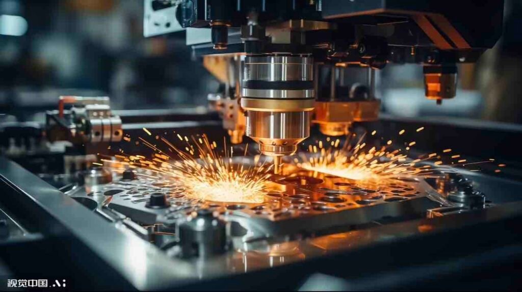
The three most common cutting methods are: laser cutting, punch press cutting, and waterjet cutting. Let’s compare their principles and characteristics
| Process | Principle | Characteristics | Applications |
| Laser Cutting | High-energy laser beams melt or vaporize metal | High precision, smooth cut edges, capable of cutting complex shapes, minimal heat-affected zone | Precision parts, small batches, and diverse product varieties |
| Punch Press Cutting | Die-Cutting | Extremely high efficiency, high precision, requires tooling | High-volume production of a single product |
| Waterjet cutting | High-pressure waterjet cutting | Cold cutting, no thermal deformation, but slow | Precision parts, special materials |
In production, laser cutting is widely used because it offers good flexibility, high accuracy, and fast programming for prototypes and mixed-part batches.
However, the best cutting method still depends on material type, thickness, edge quality requirements, hole geometry, and production volume.
Stamping is ideal for parts with many repetitive holes. Using dies to punch holes or form shapes is the most efficient method.
Waterjet cutting uses high-pressure water mixed with abrasive to cut materials. Since it does not generate heat, it is suitable for thick plates or materials sensitive to high temperatures.
Bending and Forming
Bending machines are the most common method. CNC bending machines can achieve very precise bends. One important point to note is that the bending radius must not be too small (generally at least equal to the sheet thickness), otherwise the metal may crack.
CNC bending systems can also improve repeatability by controlling backgauge position, stroke depth, and bend sequence, which is especially useful for medium- and high-volume production.
Assembly
Metal sheet components are typically joined together using welding or mechanical fasteners.
The principle of welding involves heating, applying pressure, or a combination of both to achieve atomic bonding between two separate metal pieces, forming a permanent joint.
Fusion welding is the most commonly used method for sheet metal assembly.
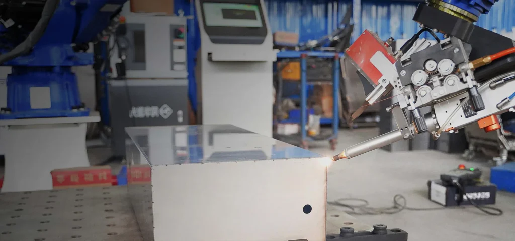
Common welding methods for sheet metal assembly include TIG (Tungsten Inert Gas) and MIG (Metal Inert Gas) welding. The right choice depends on material type, thickness, appearance requirements, heat input control, and production efficiency.
In TIG welding, the tungsten electrode serves only as an electrode and does not melt itself. During operation, the welder must manually feed the welding wire. Because this is a manual process, heat input can be controlled with greater precision; although the speed is slower, the accuracy is higher.
In MIG (Metal Inert Gas) welding, the welding wire serves as both the electrode and the filler metal. During welding, the wire is fed automatically and continuously. This continuous wire feeding results in extremely high efficiency, typically 2–5 times faster than TIG welding, making it suitable for thicker steel components and high-volume production.
Common mechanical joining methods include riveting and press-fitting: Riveting involves using rivets to join two or more workpieces together. Press-fitting involves using a press to drive fasteners such as press-fit nuts and screws into pre-drilled holes in sheet metal parts, securely embedding them in the sheet. Other methods include threaded connections, snap-fit connections, and hinged connections.
What is the surface treatment process for sheet metal?
Surface treatment is a key step in sheet metal fabrication because it affects corrosion resistance, appearance, wear performance, electrical properties, and outdoor durability. The right finish depends on the base material, service environment, cosmetic requirements, and downstream assembly needs.
Common choices vary by substrate, such as cold-rolled steel, stainless steel, and aluminum, and by end use, such as outdoor enclosures, electronic housings, or decorative parts.
| Processes | Core Principles | Suitable Substrates | Key Benefits | Scope of Application | Notes |
| Electrostatic Powder Coating | Powder is electrostatically applied and then cured at high temperatures. | Various metals (carbon steel, aluminum, stainless steel, etc.). | Cost-effective for many industrial parts. Wide color range (including custom RAL options), relatively thick coating (about 35–200 μm), and good weather and corrosion resistance when properly specified. | Appliance housings, enclosures and cabinets, outdoor equipment, automotive parts. | The most common coating method for industrial sheet metal parts. |
| Anodizing | Formation of an oxide film through electrochemical action. | Aluminum and aluminum alloys (exclusive process). | “High-end customization” for aluminum parts. The coating is hard (0.5–150 μm), wear-resistant, insulating, dyeable, and fade-resistant. | Consumer electronics (mobile phone/computer casings), aerospace, and architectural aluminum. | Enhances both aesthetics and performance. |
| Electroplating | Electrolytic deposition of an additional metal layer. | Steel, copper, etc. (must be conductive). | Combines functionality with aesthetics. Improves corrosion resistance (zinc plating), hardness and wear resistance (chrome plating), electrical conductivity (gold/silver plating), or appearance. Coating thickness: 5–25 μm. | Automotive parts, electronic components, standard parts, decorative parts. | Gives the metal entirely new surface properties. |
| Brushing | Linear patterns formed by mechanical friction. | Stainless steel, aluminum (metals where appearance is a priority). | Enhances texture and conceals scratches. Creates a fine satin finish, giving the product a more premium appearance. | Home appliance panels, electronic device casings, kitchenware, elevators. | Commonly used as the final finish for stainless steel products. |

When selecting materials, consider the following points
Cost considerations: If the environment is not overly humid, cold-rolled steel (CRS) is sufficient, and it provides excellent paint adhesion; powder coating also adheres well.
Corrosion protection: If parts are exposed to rain, condensation, salt spray, or chemical environments, material and finish selection should be evaluated together. Galvanized steel or 304 stainless steel is often suitable for general corrosion resistance, while 316 stainless steel is commonly preferred for harsher marine or chemical environments.
Lightweight requirements: Aluminum 5052 is widely used for enclosures and bent parts because of its good formability and crack resistance during bending. Aluminum 6061 offers higher strength, but in many cases it is less bend-friendly than 5052 and is often selected when machining strength or structural rigidity is more important.
Key Considerations During Design
To ensure your design drawings are successfully transformed into physical products, it is best to understand these sheet metal design rules:
Keep thicknesses consistent: Use a single thickness for a part whenever possible to simplify manufacturing.
Avoid excessively small holes: The hole diameter should ideally be no smaller than the sheet thickness; holes that are too small are difficult to punch.
Include a bend relief groove: Cutting a small notch at the bend point helps prevent tearing.
Place holes farther away from the bend line: Ideally, at least twice the sheet thickness, to prevent the holes from being distorted during bending.
Tolerances should be reasonable: Sheet metal fabrication is not machining; precision is not as high. Generally, bending tolerances are ±0.5 mm, and laser cutting tolerances are ±0.1 mm.
Tips for sheet metal assembly:
If joining dissimilar metals (such as aluminum and steel), welding can be difficult; in such cases, riveting, rivetless crimping, or threaded connections are better options .
If extremely high joint strength and rigidity are required, welding is the preferred method. For general strength requirements, riveting is fully sufficient.
If future disassembly and maintenance are required, choose removable methods such as threaded connections or snap-fit connections .
If a smooth, aesthetically pleasing surface is required, welding (especially laser welding) produces excellent results after grinding . Riveting, on the other hand, leaves raised marks on the surface.
Summary
From material selection and gauge choice to cutting, bending, joining, and finishing, sheet metal fabrication decisions are closely linked. Early communication with your supplier about material, tolerance, finish, and assembly requirements usually helps reduce rework, control cost, and improve delivery reliability.
FAQ
What are the most commonly used sheet metal thicknesses?
Generally, 18-gauge (1.2 mm) and 16-gauge (1.5 mm) are the most common choices, as they offer sufficient strength and are easy to process.
Is sheet metal fabrication expensive?
To be honest, sheet metal is quite cost-effective for medium to large-scale production, as tooling costs are significantly lower than those for die-casting or injection molding.
Can sheet metal be made waterproof?
Yes. Although metal itself is not waterproof, applying a powder coating, anodizing (for aluminum), or adding gaskets after welding can achieve IP-rated water resistance.
What materials are typically used for sheet metal products?
Common sheet metal materials include carbon steel, galvanized steel, stainless steel, aluminum, copper, and brass. The right choice depends on strength, conductivity, corrosion resistance, appearance, weight, and cost.)
Why is anodizing performed on aluminum sheets? Can they be spray-painted instead?
Anodizing is a process “exclusive” to aluminum parts. It uses electrochemistry to create a dense layer of aluminum oxide (corundum) on the aluminum surface. This layer is hard, wear-resistant, insulating, and corrosion-resistant, and can be dyed to achieve vibrant, fade-resistant colors. It is the best way to enhance the performance of aluminum parts.Of course, aluminum sheets can also be coated (such as with powder coating). However, coating merely involves applying a layer of paint to the surface; if the paint film is damaged, the underlying aluminum substrate may still be exposed to oxidation. Anodizing, on the other hand, transforms the surface into a ceramic film with inherent bonding strength.
How to save money when designing sheet metal parts?
Following these principles can effectively reduce costs:
Standardize dimensions: Minimize the variety and sizes of holes in parts, use standard-sized punches whenever possible, and reduce tool changeover time.
Simplify the structure: Whenever possible, use simple bending instead of complex drawn surfaces. Complex structures often require custom dies, which significantly increase costs.
Reasonable Tolerances: Assign wider tolerances (e.g., ±0.5 mm) to non-mating surfaces whenever possible; excessive precision requirements only increase inspection and scrap costs.
Use off-the-shelf components: Utilize commercially available rivet nuts, screws, hinges, and other standard parts instead of machining complex threaded holes or structures in-house.
Why are my screws loose and prone to turning after riveting?
There are typically two reasons for this:
Incorrect pilot hole dimensions: Rivet nuts have strict requirements for pilot holes. If the hole is too large, the nut will not undergo sufficient deformation during insertion, resulting in insufficient torque; if the hole is too small, the nut may not fit or may damage the die. Machining must strictly follow the pilot hole specifications provided by the supplier.
Sheet metal is too thin or too hard: Press-fit nuts require sheet metal of a certain thickness (typically recommended to be ≥0.8 mm) and with sufficient plastic flow capacity. If the sheet is too hard (such as high-carbon steel), the material cannot flow sufficiently to fill the knurled grooves of the nut, resulting in an insecure lock.
Why do holes in sheet metal parts sometimes deform?
Hole deformation primarily occurs after punching or bending.
Punching deformation: Worn punches or improper cutting clearances result in poor hole cross-section quality or even pull the hole out of shape. The solution is to check whether the die clearance is appropriate.
Bending deformation: If a hole is too close to a bend line, material flow during bending can pull the hole into an elliptical shape. Design specification: Generally, the distance from the hole edge to the bend edge must be at least twice the sheet thickness plus the bend radius (L > 2t + R).
What is “springback”? How can springback be minimized?
Springback is the elastic behavior of metallic materials. During bending or forming, the material undergoes both elastic and plastic deformation. When the external force is removed, the elastically deformed portion recovers, causing the actual angle of the part to be greater than the angle set by the die; this is known as “springback.”
Methods to reduce springback:
Bend compensation: When designing the die, set an angle that is smaller than the required angle (for example, if 90° is needed, make the die 88°).
Reduce the bending gap: Apply greater pressure to the material within the die to ensure it is fully formed.
Add a rib: Add a small rib near the bend line to break up stress concentrations, which can also effectively reduce springback.
Why do parts often crack during bending?
This is usually because the inner corner of the bend is designed too small, falling below the material’s “minimum bend radius.” When the material is bent, the outer side is subjected to tensile stress; if the angle is too small, the tensile stress will exceed the material’s limit, causing it to crack.
Solution:
When designing, for standard steel sheets, the inner radius (R) should be at least equal to the sheet thickness (R ≥ t).
If a right-angle bend is necessary, consider pre-pressing a “crease line” along the bend line.
The bending direction should be as perpendicular as possible to the grain direction of the material.