
The purpose of this article is to provide you with a systematic understanding of CNC machining, covering its historical development, internal structure, working principles, and the various types of CNC machining processes. If you are just beginning to explore CNC machining, this article is exactly what you need.
What is CNC Machining?
Simply put, CNC machining = digital program instructions + computer control system + automated machine tools + closed-loop feedback execution
Core Concepts of CNC Machining
To truly grasp CNC, the most intuitive approach is to contrast it with traditional manual machining and identify the key differences.
| Manual Machining | CNC Machining | |
| Operator | Focuses on drawings, relying on experience to determine feed rates, spindle speeds, and tool paths. | Prepares machining programs, clamps workpieces and tools, sets parameters, and monitors the machining process. |
| Operation Method | Manually rotate handwheels to control tool or workpiece movement along X, Y, and Z axes. | Press the start button to initiate. (The machine tool receives program commands, which the computer control system interprets and precisely drives servo motors to operate ball screws and linear motors, enabling automatic multi-axis coordinated movement of tools and workpieces.) |
| Core Dependencies | Highly dependent on the operator’s experience, concentration, and physical stamina. Part precision and consistency are significantly influenced by human factors. | Highly dependent on program accuracy and machine precision. Virtually unaffected by human intervention. |
| Part Complexity | Machining complex shapes is difficult, time-consuming, or even impossible. | Any part can be machined regardless of complexity, provided the tool can reach it and the program can describe it. |
- Program Instructions: Essentially a sequence of ordered codes (commonly G-codes and M-codes). These instructions precisely dictate: tool path (straight lines, arcs, curves), movement speed (feed rate F), spindle speed (spindle speed S), tool change (M06), coolant activation (M08/M09), etc.
- Automatic Execution: The machine tool’s CNC system (CNC controller) acts as the “executor.” Its function is to read the program code and convert it into electrical signals that drive the servo motors. These motors then move the lead screws and linear motors, causing the worktable and cutting tools to perform machining actions. High-precision position feedback devices monitor the spindle and worktable positions in real time, ensuring their movements are accurate and precise.
It can be said that CNC machining represents a leap from manual control to computer numerical control. Traditional machining heavily relied on the experience and tactile skills of craftsmen, whereas CNC machining shifts human judgment and manual operations to computers and servo systems. Workers no longer need to turn handwheels; instead, they focus their energy on writing and generating program instructions.
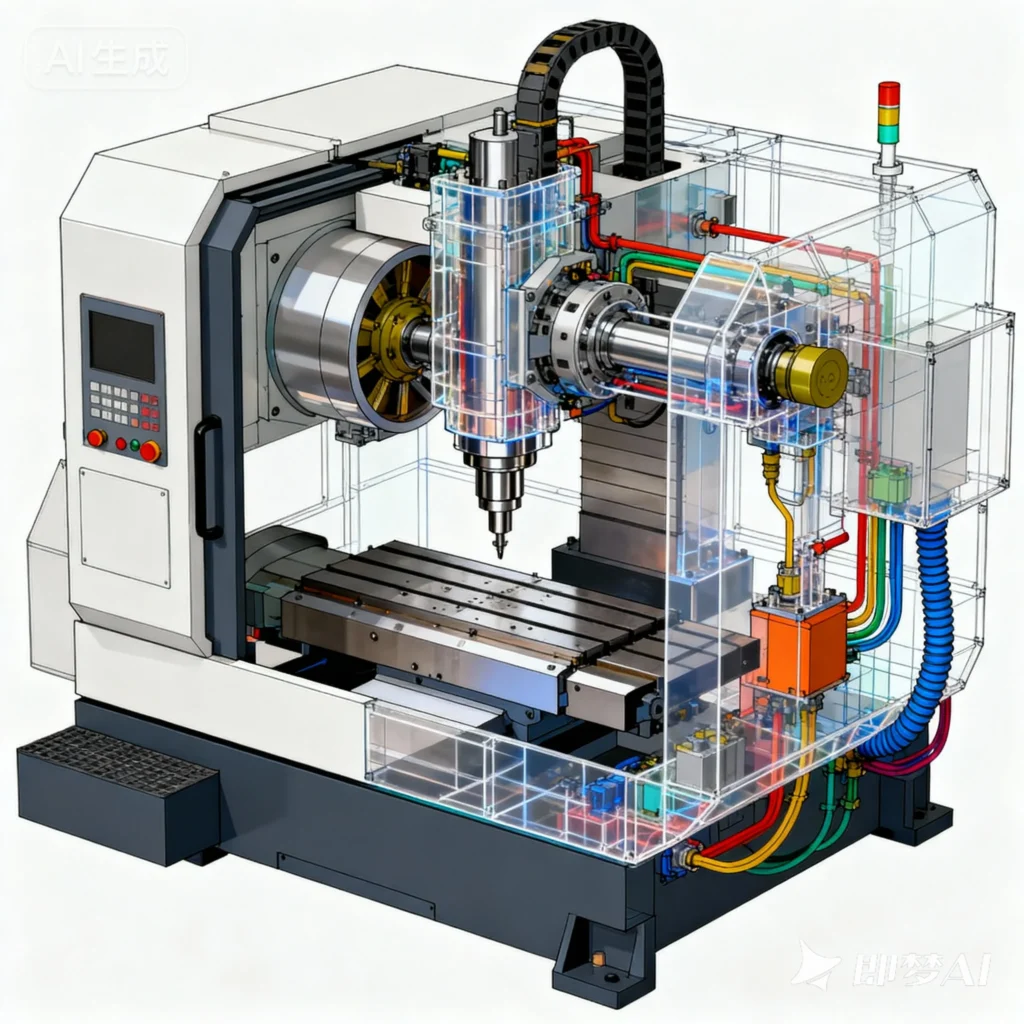
Core Components of CNC Machine Tools
- Machine Tool: This serves as the physical platform that houses CNC components and executes all movements. Compared to traditional machine tools, it is more precise and structurally robust.
- CNC Controller: Considered the machine’s “central nervous system,” it interprets programs, calculates motion trajectories, controls axis movements, and processes I/O signals for functions like tool changes and coolant delivery.
- Servo Motor: Equivalent to the machine tool’s “heart,” it provides power for the spindle and worktable movements.
- Servo Drive: The machine’s regulation system, receiving commands from the CNC controller to adjust motor speed, position, and torque.
- Feedback Devices: Primarily monitor real-time position, direction, and speed of each axis, transmitting this information back to the CNC controller.
- Spindle System: The most critical and direct axis driving tool or workpiece rotation. Includes the spindle motor, spindle bearings, etc.
- Automatic Tool Changer (ATC): A signature component of machining centers, it automatically exchanges tools between the tool magazine and spindle according to program instructions, enabling continuous processing of multiple operations.
- Work Table/Fixture System: Primarily functions to position and clamp the workpiece.
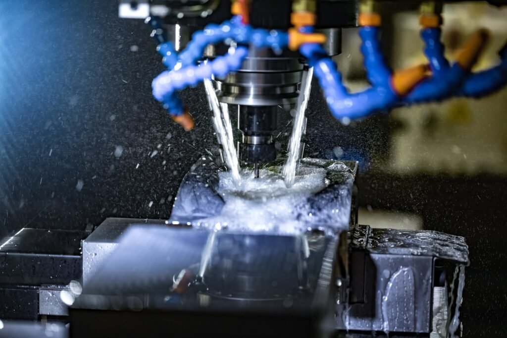
- Coolant/Lubrication System: Supplies cutting fluid to cool tools and workpieces while flushing away metal chips and reducing friction.
Types of CNC Machining
Classified by Machining Method
CNC Lathe
CNC lathes are arguably the most fundamental machines in the CNC machining system. They primarily clamp workpieces (typically cylindrical blanks) onto a spindle for high-speed rotation, while cutting tools feed radially (X-axis) and axially (Z-axis) to perform machining. They are mainly used for processing rotary parts like flanges and bushings.
CNC lathes are simple and stable, yet capable of efficient part machining. They excel at processing external circles, internal bores, end faces, grooves, and threading.
CNC Milling Machine
The tool is mounted on the spindle and moves vertically (Z-axis), while the workpiece rests on a table capable of planar movement (X, Y-axes). The spindle controls the tool’s height, and the workpiece is machined by moving the table. Primarily used for machining flat surfaces, slots, contours, and complex three-dimensional surfaces (e.g., molds, housings).
CNC milling machines also include the following three common subtypes:
- Vertical Machining Centers: Evolved from CNC milling machines, featuring a vertical spindle orientation and processing through X/Y-axis worktable movement. Equipped with automatic tool changers, tool magazines, and program control, they enable multi-process continuous machining. Ideal for molds, housings, and plate-type components.
- Horizontal Machining Centers: Featuring a horizontal spindle orientation and a rotary worktable. This design enables machining of four or even five surfaces in a single setup, facilitates easy chip removal, and is particularly suited for box-type components. However, it occupies a larger footprint and carries a higher price tag.
- Gantry Machining Center: The spindle is vertically oriented and can move along both the Z-axis and Y-axis, supported by a gantry frame. Designed specifically for machining large, heavy components, it features high rigidity and extensive travel ranges.
CNC Drilling Machine
This machine specializes in efficient hole machining operations such as drilling, reaming, boring, and tapping. Its structure is relatively simple, yet it delivers exceptionally high efficiency.
CNC Grinding Machine
Primarily utilizes grinding wheels to perform precision grinding on workpieces, achieving extremely high surface finish and dimensional accuracy. Suitable for finishing difficult-to-machine materials like hardened steel.
CNC Wire Cutting Machine
This machine tool operates without cutting tools, instead using a continuously moving fine metal wire (electrode wire). It melts metal by generating instantaneous high temperatures through pulsed spark discharges between the wire and the workpiece. Requiring no contact and producing no cutting forces, it is suitable for machining extremely hard materials.
Classification by Number of Axes
- 2-axis: The most basic linkage, featuring only X and Y axes. It has significant limitations and is suitable for simple machining operations.
- 3-axis: The most common 3-axis linkage (X, Y, Z axes) can machine most three-dimensional surfaces, though dead zones remain on the bottom and sides.
- 4-axis: Adds a rotational axis (A-axis rotating around X or B-axis rotating around Y) to the 3-axis (X, Y, Z) setup. Enables machining multiple surfaces of a part in a single setup.
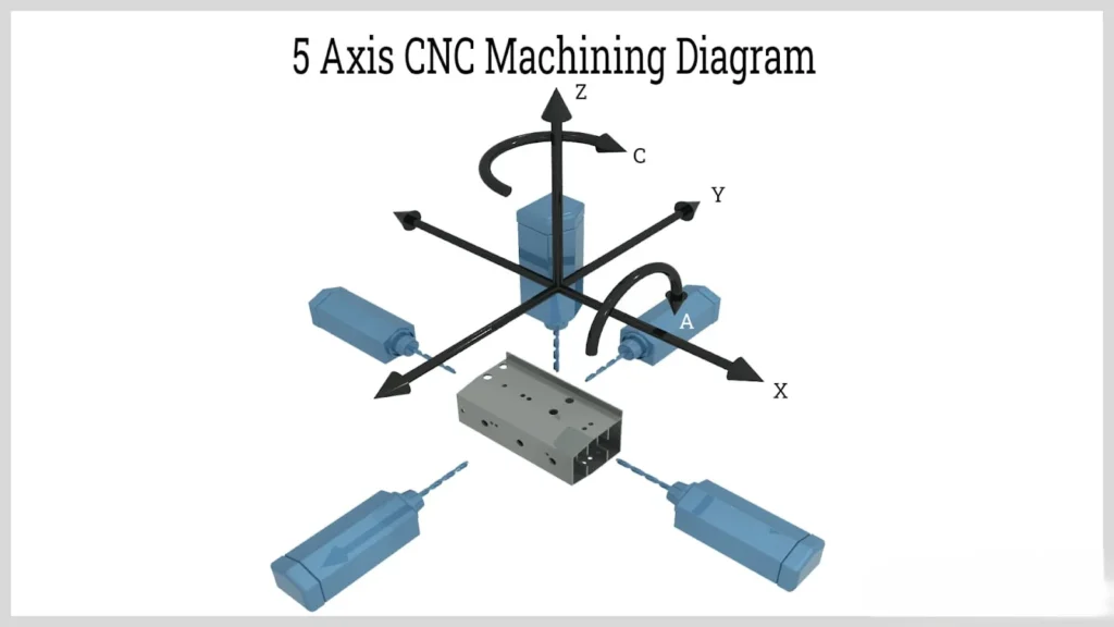
- 5-axis: Adds two rotary axes to the 3-axis (X, Y, Z) system (common combinations include A-axis rotation around X + C-axis rotation around Z; or B-axis rotation around Y + C-axis rotation around Z). 5-axis represents advanced CNC machining, enabling the production of highly complex components.
Characteristics and Applications of CNC Machining
Characteristics of CNC Machine Tools
CNC machine tools execute part machining processes strictly according to the parameters and actions specified in the machining program. As highly efficient automated machines, they exhibit the following distinct characteristics compared to conventional machine tools:
- Suitable for processing complex irregular parts. CNC machine tools can complete the machining of complex parts that are difficult or impossible for conventional machine tools to process, thus finding widespread application in industries such as aerospace, shipbuilding, and mold manufacturing.
- High machining precision.
- Stable and reliable machining. By eliminating human error, parts exhibit consistent machining results with stable and reliable quality.
- High productivity. CNC machine tools inherently possess high precision and rigidity, allowing selection of optimal machining parameters. This results in high production efficiency, typically 3 to 5 times that of conventional machine tools. For certain complex parts, productivity can increase by a factor of ten or even several dozen times.
- Improved working conditions. Operator workload is significantly reduced, and the work environment is more favorable.
- Facilitates modernized management. Adopting CNC machine tools promotes the development of computer-controlled production management, creating conditions for achieving production automation. Its disadvantages include: high investment and operating costs; complex production preparation tasks such as process planning, toolpath planning, and program development; and high maintenance costs.
Scope of Application for CNC Machine Tools
When selecting machining equipment and developing part processing techniques, factors such as superior quality, high efficiency, and low cost must be considered. Therefore, a well-designed machining process should be chosen based on the actual characteristics of the available equipment. Given the aforementioned features of CNC machine tools, parts suitable for CNC machining include:
- Parts that cannot be machined by conventional machines should be prioritized, such as those with complex geometric shapes.
- Parts that are difficult to machine on conventional machines and where quality assurance is challenging should be prioritized, such as high-precision batch parts requiring high part consistency.
- Parts with low machining efficiency on conventional machines and high labor intensity for manual operation can be selected when CNC machines have spare processing capacity.
Generally, adopting CNC machining for the above scenarios yields significant improvements in product quality, production efficiency, and overall benefits.
In contrast, CNC machining is not suitable for the following scenarios:
- Long machine setup times. For example, machining the first precision reference from a rough reference using a rough blank requires specialized fixtures for coordination.
- Processing locations are dispersed, requiring multiple setups and origin adjustments. In such cases, CNC machining becomes cumbersome with limited benefits; conventional machine tools may be used for supplementary processing instead.
- Surface contours machined based on specific manufacturing references (e.g., templates). The primary reasons are difficulty in data acquisition, potential conflicts with inspection criteria, and increased programming complexity.
- Rough machining with large and uneven allowances.
Additionally, when selecting and determining machining operations, factors such as production batch size, production cycle, and inter-process turnaround must be considered. In summary, efforts should be made to achieve rationality, aiming for high volume, speed, quality, and cost-effectiveness. Avoid degrading CNC machines to general-purpose machine tools. Selecting CNC machining content according to the above principles maximizes the advantages of CNC processing.
Fundamentals of CNC Machining Programming
Content and Methods of CNC Programming
When machining parts on a CNC machine, first record all process steps, parameters, displacement data, directional information, and operational sequences from the part drawing onto a control medium (e.g., USB drive) using specified codes and program formats. This digital information is then transmitted to the CNC unit, directing the machine to execute the predefined design.
Steps in CNC Programming
Determining the Machining Process
When determining the machining process, you must analyze the part drawing to select a machining plan. This involves establishing the machining sequence, toolpath, clamping method, cutting tools, and cutting parameters.
Numerical Calculation
Calculate the data required for input into the CNC device based on the determined machining path and permissible part machining tolerances. The main content of numerical calculation is: calculating the coordinate values of the part contour and tool movement trajectory within the specified coordinate system.
Parts Machining Program Sheet Preparation
You must write the part processing program sheet according to the functional instruction codes and program format specified by the CNC system. Additionally, you need to complete related process documentation, such as CNC machining process cards, CNC tool cards, and CNC tool lists.
Control Media
Record the compiled program onto a control medium as input data for the CNC device. Common options include USB drives and TF cards. Direct keyboard input is also possible. Some equipment supports transmission via network cables or wireless connections.
Program Verification and Test Cutting
The compiled machining program must undergo verification and a test cut of the part. By comparing the shape and dimensions of the test piece with the drawing, the program and process parameters are validated. Only when full compliance is achieved should formal machining commence.
Methods for CNC Program Development
There are two primary methods for creating CNC programs: manual programming and automatic programming.
- Manual Programming: The entire programming process is completed manually. For parts with relatively simple geometric shapes, straightforward numerical values, and few program segments, manual programming is easier to accomplish, economical, and timely.
- Automatic Programming: Also known as computer-aided programming, this method utilizes specialized software to generate CNC machining programs. Based on the drawn part drawings, automatic programming software performs numerical calculations and post-processing, automatically compiling the part machining program. The machining program is then transmitted to the CNC machine tool via a transfer medium to direct its operation.
CNC Program Format
A part machining program consists of a program name and multiple program segments. Each program segment comprises a segment number and several instructions. Each instruction is composed of letters, symbols, and numbers. Each program segment is terminated by a semicolon (;), making the program segment the fundamental unit of a CNC program. For example:
Program Name: 08008;
N0010 G54 G98;
M03 S1000;
N0030 T0100;
N0080 G00 X40 Z10;
N0050 G01 X0 Z10;
Note:
- Program naming conventions vary across different CNC systems; refer to the actual manual for specifics.
- Program blocks begin with the sequence number “Nxxxx” and end with a semicolon (;). Each block represents a complete machining operation.
- The sequence number is optional. The spacing between two sequence numbers can be arbitrary. There is no sorting requirement; the order can be random.
Function Code Overview
Part machining programs consist of individual program blocks, which are composed of program characters. Program characters are divided into dimension characters and function characters. Function characters, also known as function codes or function instructions, form the core components of program blocks. Common function codes include preparatory G codes and auxiliary M codes. Additionally, there are feed rate F codes, spindle speed S codes, and tool function T codes.
Preparatory Function G-Codes
Commonly referred to as G-code or G-instructions, these commands establish specific machining modes between the machine tool and CNC system. They must be pre-set before machining to prepare the processing method—whether linear or circular interpolation, along which plane the tool will move, etc. G-code comprises 100 types, ranging from G00 to G99.
G-codes are categorized into modal and non-modal types
- Modal Commands (Persistent Commands): These commands remain active throughout a program segment until overridden by another command within the same group. Each command group can only appear once per segment; otherwise, only the last code takes effect. Modal commands need only be specified once during use and do not require repetition in subsequent segments.
- Non-modal commands (non-persistent commands): These commands remain active only within the program segment where they are used. To continue using the function, it must be re-specified in subsequent program segments.
Auxiliary Function M Codes
Auxiliary M codes are process instructions defined according to machine tool requirements. They control auxiliary machine actions, primarily serving as process-specific commands during machining operations—such as spindle rotation, coolant activation/deactivation, and workpiece clamping/unclamping. There are 100 types ranging from M00 to M99.
F, T, S Commands
- Feed Rate Command F: Consists of the letter F followed by numerals indicating the actual machining speed. Units are mm/min or mm/rev. For example, F100 denotes a feed rate of 100 mm/min.
- Tool Function Code T: Consists of the letter T followed by a four-digit number. The first two digits denote the tool number, and the last two digits denote the tool compensation number. If the last two digits are 00, it indicates cancellation of the tool compensation value. For example, T0101 calls tool number 01 and applies tool compensation number 01; T0100 calls tool number 01 and cancels the tool compensation value.
- Spindle speed command S: Consists of the letter S followed by a number indicating the spindle rotation speed in r/min. For example, S800 specifies a spindle speed of 800 r/min.
Coordinate System of CNC Machine Tools
Machine Coordinate System
- ISO Standard Specifies: The workpiece is always assumed stationary, with the tool performing feed motion relative to the workpiece. Programming is based on the tool’s motion path.
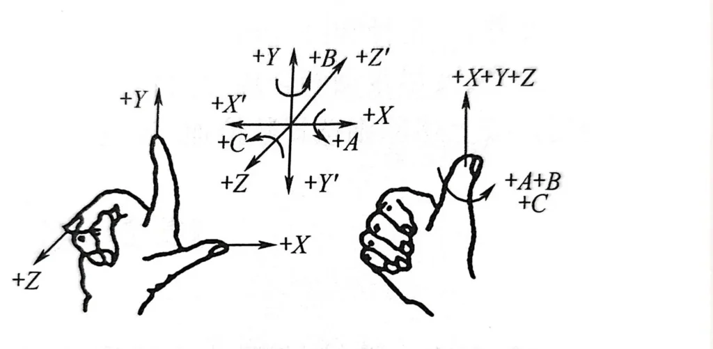
- Following the right-hand rule: X, Y, and Z represent the basic coordinate axes. The middle finger corresponds to the Z-axis, the thumb to the X-axis, and the index finger to the Y-axis. Circular feed axes rotating around the X, Y, and Z axes are denoted by A, B, and C. According to the right-hand screw rule, when the thumb points toward the +X, +Y, and +Z directions, the direction in which the four fingers bend corresponds to the +A, +B, and +C directions of circular feed motion, as shown in Figure 3.
- Direction: The positive direction is away from the workpiece.
Machine Origin and Coordinate System
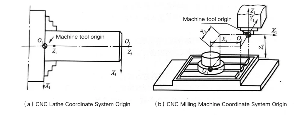
The machine origin’s position is determined by the machine tool manufacturer and is a fixed point on the machine. For CNC lathes, the machine origin is typically defined at the intersection of the spindle rotation center and the rear face of the chuck. For CNC milling machines, the machine origin is usually defined at the center point of the worktable surface or at the limit position of the positive direction of the X, Y, and Z axes, as shown in Figure 4.
The coordinate system established with the machine tool origin as its origin is the machine tool coordinate system. It serves as the foundation for manufacturing and adjusting the machine tool and generally should not be arbitrarily altered.
Reference Points and Reference Coordinate Systems
When the CNC unit powers on, it does not know the machine origin. To correctly establish the machine coordinate system during operation, a machine reference point (measuring starting point) is typically set within the travel range of each coordinate axis. Upon machine startup, a motorized or manual return to the reference point (also called zero return) is usually performed to establish the machine coordinate system. The distance between the machine reference point and the machine origin is specified through parameters set in the machine system.
Workpiece Coordinate System (Programming Coordinate System)
This coordinate system, along with the program origin, is used by programmers during programming. The programmer selects a known point on the workpiece as the origin (also called the program origin) to establish a new coordinate system, known as the workpiece coordinate system. Once established, the workpiece coordinate system remains valid until replaced by a new one.
The origin selection for the workpiece coordinate system should prioritize simplicity in programming, minimize dimensional conversions, and reduce machining errors.
Generally, the program origin should be selected on a dimensioning reference or locating reference.
Absolute Coordinate Programming vs. Relative Coordinate Programming
- Absolute coordinate programming refers to coordinate values relative to the origin of the programming coordinate system.
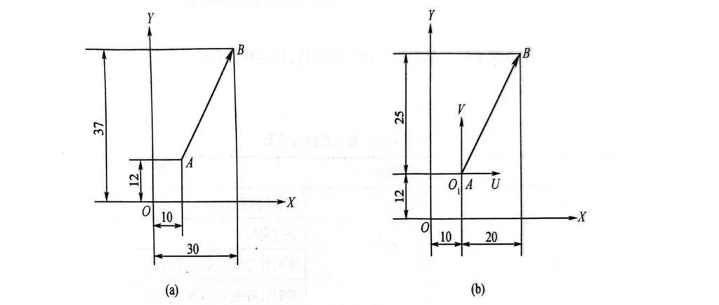
- Relative coordinate programming means coordinate values are given relative to the previous position. During calculation, the coordinates of the current point are determined by the difference between the coordinates of the next point and the previous point. Typically, X, Y, Z represent absolute coordinates, while U, V, W represent relative coordinates. Within the same program segment, X and U, or Y and V, or Z and W can be used interchangeably. In CNC milling programming, G90 X_Y_Z_ denotes absolute coordinates, while G91 X_Y_Z_ denotes relative coordinates. As shown in the figure, the absolute programming code for (a) is: G90 G00 X30 Y37; the relative programming code for (b) is: G91 G00 X20 Y25.
CNC Machining Process Principles
Roughing Before Finishing
To enhance production efficiency and ensure part finishing quality, roughing operations should be scheduled first. This rapidly removes substantial roughing stock before finishing while striving to meet uniformity requirements for finishing stock.
If the uniformity of the remaining allowance after rough machining fails to meet finishing requirements, a semi-finishing operation can be scheduled as an intermediate step. This ensures a smaller and more uniform finishing allowance, thereby satisfying the finishing allowance requirements.
Near-first, far-last
The term “near” and “far” here refers to the relative position of the machining area to the starting point. Generally, especially during rough machining, areas closer to the starting point are processed first, while those farther away are processed later. This minimizes tool travel distance, reduces idle time, and improves the rigidity of the blank or semi-finished part, thereby enhancing cutting conditions.
Inner Surfaces Before Outer Surfaces
For parts requiring both internal (inner profiles, cavities) and external surface machining, internal surfaces should typically be machined first, followed by external surfaces. This is because controlling internal surface dimensions and geometry is more challenging, tool rigidity is lower, heat dissipation within internal cavities is difficult, cutting edge durability is more susceptible to reduced tool life due to cutting heat, and chip evacuation during machining is more difficult.
Shortest Toolpath
While ensuring machining quality, selecting the shortest possible tool path not only reduces overall processing time but also minimizes unnecessary tool wear and wear on the machine tool’s feed mechanism sliding components.
CNC Lathe Machining Program Example
Next, we’ll guide you through writing a machining program for a part. Assuming a blank diameter of 100 mm bar stock, roughing allowances are: U+=0.5, W+=0, and cycle count R=25. The maximum removal in the X-axis is U=(100-0-0.5)/2=49.75, while the maximum removal in the Z-axis is W=0.
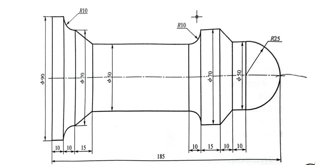
Below is the machining program we wrote, along with comments for each program segment.
08008; ——//Program name.
N20 M03 S1000; ——//Start spindle clockwise rotation at 1000 r/min.
N30 T0100; ——// Change to tool 01.
N40 G00 X110 Z10; ——// Rapidly move to the starting point.
N50 G73 U49.75 W0 R25 F100; ——// Rough turning cycle.
N60 G73 U0.5 W0 P70 Q170; ——//Rough turning cycle.
N70 G00 X0 Z10; ——//Rapid traverse.
N80 G01 20; ——//Machine straight line.
N90 G03 X50 Z-25 R25; ——//Machine arc.
N100 G01 Z-35; ——//Machine straight line.
N110 X70 Z-45; ——//Machine straight line.
N115 Z-60; ——//Machine straight line.
N120 G02 X50 Z-70 R10; ——//Process arc.
N130 G01 Z-150; ——//Machine straight line.
N140 X70 Z-165; ——//Machine straight line.
N150 G02 X90 Z-175 R10; ——//Process arc
N160 G01 Z-185; ——//Machine straight line
N170 G00 X110; ——//Rapid retract.
N180 G70 P70 Q170 F50; ——//Finish turning cycle.
N190 G00 X110 Z10; ——//Rapid return to starting point.
N200 M05; ——//Spindle stop.
N210 M30; ——// Program stops completely and returns to the program header.
Materials Suitable for CNC Machining
CNC machining is truly versatile—capable of processing metals, plastics, composites, and even wood. To put it another way: CNC’s machining capability doesn’t depend on the material itself, but rather on selecting the appropriate tooling, processes, cooling, and machine performance for that material. For example:
Stainless Steel
Stainless steel is characterized by corrosion resistance and high toughness, but it is difficult to machine, exhibits severe work hardening tendencies, and has poor thermal conductivity. Therefore, when machining stainless steel, specialized tools designed for this material must be used, and constant, adequate feed rates and coolant application must be maintained.
Titanium Alloys
Titanium alloys are notoriously difficult to machine due to their extreme strength and poor thermal conductivity. During machining, heat concentrates at the tool tip, causing rapid tool wear. When machining titanium alloys, use lower cutting speeds, sharp carbide tools, and ample coolant.
Engineering Plastics
Engineering plastics are lightweight, corrosion-resistant, and insulating. However, they exhibit poor thermal conductivity, are heat-sensitive, and prone to deformation. When machining engineering plastics, control rake heat to prevent softening or melting. Also, pay attention to clamping force during setup.
Applications of CNC Machining
From traditional manual machining to high-precision CNC processing, it is virtually ubiquitous across every industrial sector. This is precisely due to its nearly limitless adaptability and unparalleled precision.
Aerospace Industry
This sector demands exceptionally stringent part specifications and extensively utilizes difficult-to-machine materials like titanium alloys, high-temperature alloys, and high-strength aluminum alloys. Components such as turbine blades, compressor disks, and landing gear assemblies feature complex geometries and thin walls, requiring highly precise machining equipment for fabrication.
Automotive Industry
In the automotive sector, it’s fair to say that without CNC machining, the entire industry would grind to a halt. This underscores its pivotal role. Many core mechanical components are CNC-machined, including engine blocks, cylinder heads, crankshafts, transmission housings, gears, and steering knuckles. Moreover, CNC serves as the core technological backbone enabling automation, mass production, and high-quality manufacturing in the automotive industry.
Medical Device Sector
In this sector, precision equates to reliability, directly impacting patient safety, health outcomes, and comfort. Components like artificial joints, bone plates, and bone screws demand extreme accuracy and exceptionally smooth surfaces. These parts are typically crafted from titanium alloys, cobalt-chromium alloys, and medical-grade stainless steel.
Mold Manufacturing
Molds are essential for producing parts in die casting, stamping, precision casting, forging, and rubber damping applications. CNC machining is the only viable method for manufacturing high-precision molds, whose accuracy directly determines product quality. Without machining, mold production would rely solely on laborious manual grinding, a highly inefficient process.
Summary
This concludes the article. If you notice any omissions, please feel free to point them out.
If you’re seeking precision machining services, consider contacting EVERGREEN Machinery. We possess a comprehensive range of machining equipment, including CNC lathes, 2-axis, 3-axis, 4-axis, and 5-axis machining centers, turning-milling centers, horizontal machining centers, gantry machining centers, and laser cutting systems. We offer one-stop precision machining solutions: from design to prototyping, small-batch trials, and full-scale production.